Electrostatic Solutions Ltd
Tel: +44 (0)23 8090 5600
Tel: +44 (0)23 8090 5600

| Electrostatic Solutions Ltd
Tel: +44 (0)23 8090 5600 |
Finite Element modeling of electrostatic fieldsFinite Element modelling provides a powerful tool for visualisation of fields in an electrostatic system. Using FE techniques the designer can rapidly investigate the performance of electrode system designs early in the development stage. Alternative designs and modifications can be evaluated, giving a high degree of confidence in the performance, before a prototype system is constructed.
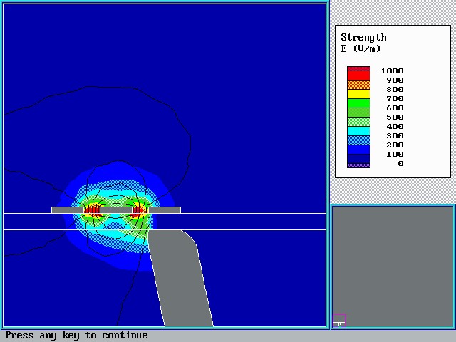
Above: A guarded touch sensitive electrode system (above) behind a plastic panel (horizontal band) is approached by a finger from below. Colour bands represent electric field with red as the highest and blue the lowest field strength. The black lines are contours of equal electric potential (voltage).
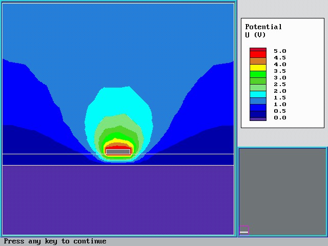
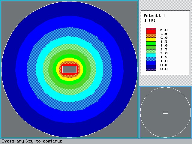
Above: A conductor at elevated voltage separated from a ground plane by a dielectric layer, for example a track on a double sided circuit board. The colour bands indicate electric potential (voltage). Below: A coaxial rectangular conductor at elevated voltage within a circular grounded outer electrode. The colour bands indicate electric potential.
Electrostatic Solutions offers 2-d and 3-d geometry electrostatic modeling using high performance FE software. Typical applications include;
|
|
| Send mail to webmaster@static-sol.com with questions or comments about this web site. Copyright © Electrostatic Solutions Ltd Last modified: December 9, 2007 |
Site designed by Very Sensible web design ©2008 |